Authors:
Jiahao Wu、Lu Xiao、Chao Wang、Rui Peng、Kaiqiang Xiong、Ronggang Wang
Paper:
https://arxiv.org/abs/2408.06543
Introduction
In recent years, significant progress has been made in 3D reconstruction technology, particularly with the advent of neural radiance fields (NeRF). However, reconstructing high dynamic range (HDR) radiance fields from low dynamic range (LDR) images remains a challenge. Traditional methods either rely on grids and spherical harmonics, which are memory-intensive, or use implicit multi-layer perceptrons (MLPs), which are slow and prone to overfitting. This paper introduces High Dynamic Range Gaussian Splatting (HDRGS), a novel method that leverages Gaussian Splatting for efficient and high-quality 3D HDR reconstruction.
Method
Preliminary
HDRGS begins with a sparse point cloud generated from Structure-from-Motion (SfM). This method models geometric shapes using 3D Gaussian functions defined by covariance matrices and means in world space. The projection of these 3D Gaussians into 2D image space is approximated as 2D Gaussians, which are then used to compute pixel values.
Basic Process
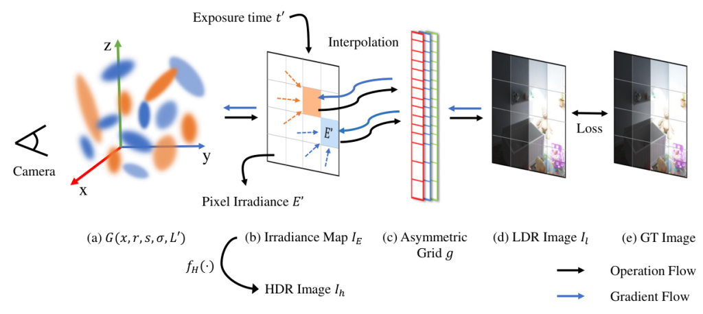
The radiance emitted by objects in the scene is transformed into irradiance on the image sensor. This process is simulated by redefining the color of Gaussian points as radiance, resulting in pixel values representing irradiance rather than color. The total irradiance received by the sensor is then converted to LDR pixel values using a camera response function (CRF).
Grid-based Tone Mapper
To simulate the physical imaging process, an asymmetric grid-based tone mapper is introduced. This grid models the process from pixel irradiance to color, offering greater flexibility and expressiveness compared to symmetric grids. The grid is designed to handle uneven distributions of irradiance values, ensuring accurate mapping and preventing overfitting.
Coarse to Fine Optimization Strategy
A coarse-to-fine strategy is employed to mitigate the grid’s discrete nature and prevent local optima. During the coarse phase, a fixed sigmoid function is used as the tone mapper, and only the attributes of Gaussian points are trained. In the fine phase, the grid is used as the tone mapper, and its parameters are co-learned with the Gaussian points.
Loss Function
The total loss function combines reconstruction loss, smooth loss, and unit exposure loss to ensure consistency and high-quality HDR radiance fields. The reconstruction loss constrains the Gaussian points, the smooth loss ensures the grid conforms to CRF properties, and the unit exposure loss aligns the HDR radiance fields with those generated by Blender.
Experiments
Implementation Details
The model is trained on an NVIDIA A100 GPU, with the coarse phase taking under 1 minute and the fine phase taking approximately 4-8 minutes. The dataset consists of 8 synthetic scenes rendered by Blender and 4 real scenes captured by digital cameras, each with 5 exposure levels.
Evaluation
The proposed method is compared with several baseline methods, including NeRF, NeRF-w, HDRNeRF, HDR-Plenoxel, and 3DGS. Metrics such as PSNR, SSIM, LPIPS, HDR-VDP, PUPSNR, PUSSIM, and FPS are used for evaluation. The results indicate that HDRGS achieves state-of-the-art performance in both synthetic and real-world scenarios, with faster training speeds and higher rendering quality.
Conclusion
HDRGS is a novel method for reconstructing 3D HDR radiance fields from 2D multi-exposure LDR images. By redefining the color of Gaussian points as radiance and using an asymmetric grid-based tone mapper, HDRGS achieves efficient and high-quality HDR reconstruction. The coarse-to-fine strategy further enhances model convergence and robustness. Experimental results demonstrate that HDRGS surpasses current state-of-the-art methods in both efficiency and quality.
Illustrations
Figure 1: Illustration of HDRGS. We redefine the color of Gaussian points as radiance L, enabling it to meet the primary requirement for reconstructing the HDR radiance field. After splatting, pixel irradiance E′(p) is obtained. Then, the differentiable asymmetric grid g maps the exposure under exposure time t to LDR pixel color. The HDR image Ih can be derived by applying the function fH(·) to each E′, with detailed explanations provided in subsequent sections.
Figure 2: The distribution of accumulated exposure. The x-axis represents the exposure values from a given camera viewpoint, and the y-axis represents the number of pixels with the corresponding exposure values. (a) represents the original distribution of accumulated exposure, while (b) represents the distribution after applying time scaling ft(·).
Table 1: Quality Comparison. LDR-OE represents the use of LDR images with exposures {t1, t3, t5} as the training set, while LDR-NE represents the use of LDR images with exposures {t2, t4} as the training set. The exposure times of the test dataset are {t1, t2, t3, t4, t5}. HDR denotes the HDR results. The best and the second best results are denoted by red and blue.
Figure 3: Comparison of LDR Image Quality for Novel View Renderings. The image in the top right of each rendered image is a zoomed-in section selected by the red rectangle. The mse error heatmap for each rendered image is shown in the bottom right. “Ours” represents our method without Lu.*
Figure 4: Comparison of HDR image quality for novel viewpoints on real scenes. The first row is GT LDR images, the second row HDR images are rendered by HDRNeRF[16], and the third row is ours.
Figure 5: Comparison of HDR image quality for novel viewpoints on syn scenes. (a) represents the GT HDR images, (b) depicts the HDR images rendered by HDRNeRF[16], while the right side (c) shows their error maps drawn by HDR-VDP. (d) presents the HDR images rendered by our method, and (e) displays the error maps of ours.
Table 2: Some ablation studies of our method.
Limitations
While HDRGS achieves impressive results, it simplifies some aspects of the physical imaging process, such as the influence of aperture size and ISO gain. Additionally, the method currently exhibits subpar reconstruction results for scenes containing transparent objects.
Future Work
Future research could focus on addressing these limitations by incorporating more detailed physical imaging models and improving the handling of transparent objects. The code and data for HDRGS will be made available to facilitate further exploration and development in this field.
Code:
https://github.com/wujh2001/hdrgs

